Smart Buoy — Scheduling Power to the System🔋⌛
A tech focused education and services company.
This Smart Buoy series charts our (ambitious) attempt to build a scientific buoy that can take meaningful measurements about the sea using off-the-shelf products. This is tutorial three of four— make sure you’re up to date, and if you need a swift introduction to the project, check out our summary.
Part 1: Making wave and temperature measurements
Part 2: GPS, Radio (NRF24) and SD Card Module
In this tutorial, we move onto the next challenge in our Smart Buoy project: how to control the power for it!
We didn’t need the Buoy to constantly take measurements — a few at regular intervals was plenty. Intermittent operation does make powering it slightly easier, because it can be off occasionally.
Another thing which simplified the powering process was the small size of the Buoy and its sensors, meaning we were able to use small, low power solar panels. However, this meant we needed to manage the little power we had effectively, to ensure the Buoy could take regular measurements throughout the day. We decided that we wanted to schedule the power to the Buoy based on how much energy there was in the battery.
Supplies
18650 Battery —Amazon
Buck booster — Amazon
Charge controller — Amazon
Solar panel — Amazon
Blocking diodes — Amazon
Power monitoring module —Amazon
Real time clock —Amazon
Arduino — Amazon
P-channel transistor — Amazon
🔗 Get The Smart Buoy Code On Github 📔
Tutorial 🤖
Powering the Buoy
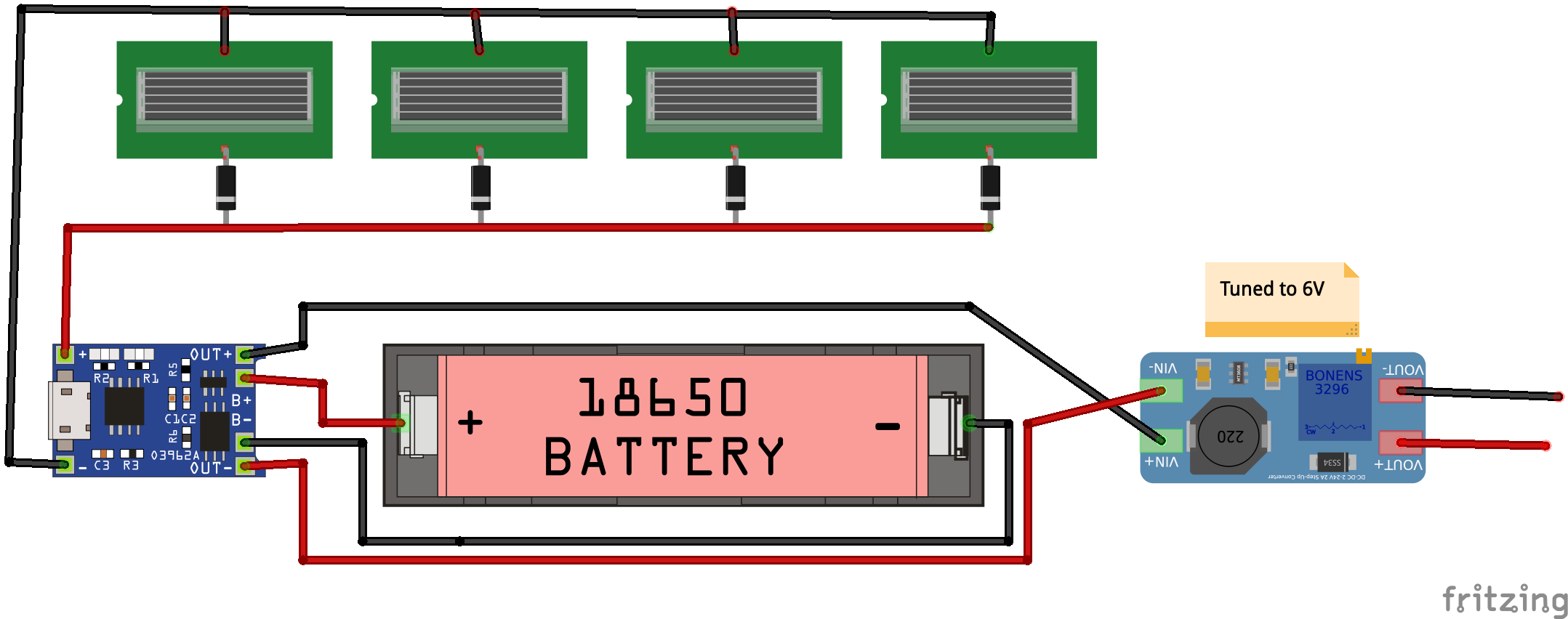
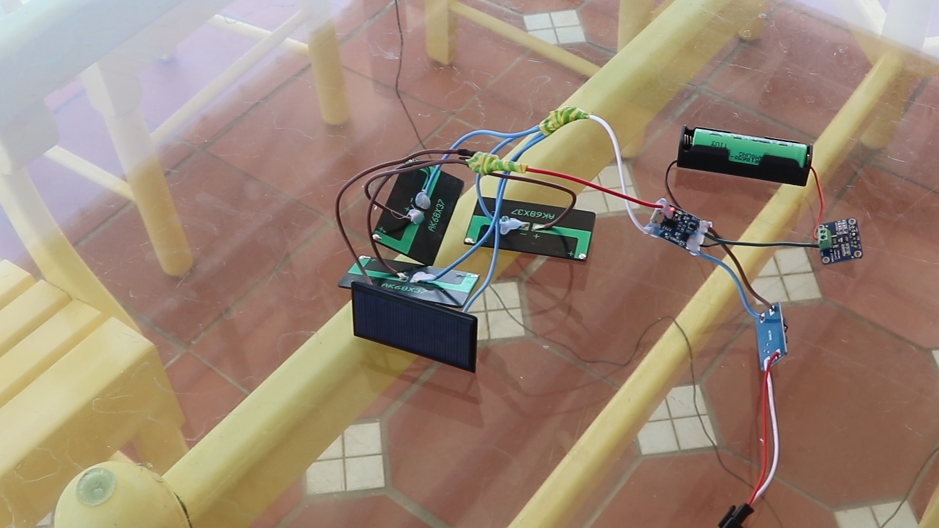
We powered the Smart Buoy using a 18650 battery, which was charged by four, 5V, 60mA solar panels in parallel. In our design, the four solar panels sit around the top of the Buoy, capturing maximum sunlight.
We put in some blocking diodes to prevent reverse current into the panels. We used a charge controller to control the battery output and charge from the solar panels. The charge controller output isn’t high enough to power the system stably, so we used a buck booster to increase the voltage to about 6V.
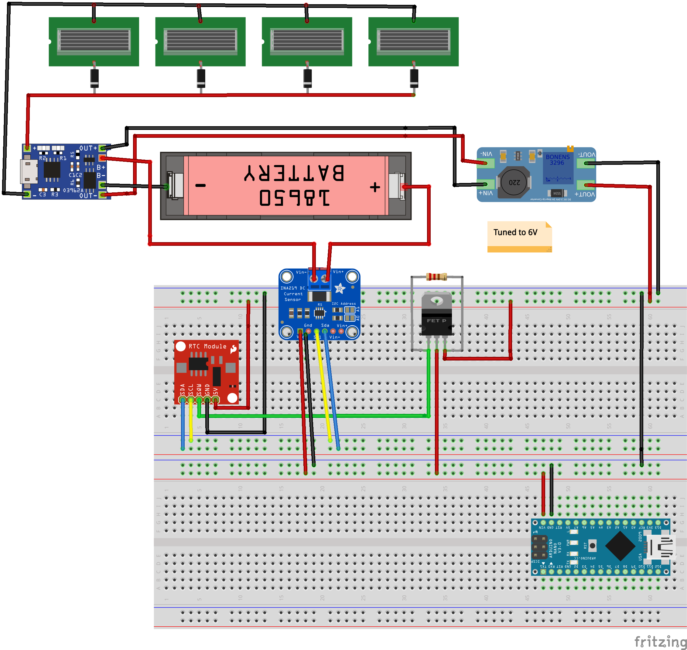
As a solely solar-powered device, it’s unlikely the Buoy would make it through the night with enough power to continue taking measurements. To ensure it always had enough power to operate the sensors, we used a real time clock module to turn the system on and off. This module was battery operated, but used such a low amount of current it could run for years.
We programmed the real time clock module to have an alarm, set based on how much power is in the battery. This value was inferred based on the battery voltage which was measured using a power monitor module. When the alarm was triggered, it changed the alarm pin from high to low. We used this to turn on a transistor, which allowed power to the arduino. The system then took its measurements and turned off by clearing the alarm and changing the pin back to high, which turned the transistor off.

Controlling Power Using the RTC Alarms
Here’s an example of how to programme an alarm to control power to the Arduino. In this example, we demonstrate using an Arduino to turn on an LED for three seconds, set an alarm for 15 seconds and then turn itself off. Once 15 seconds have passed, the alarm triggers, the LED turns on again and the cycle repeats.

#include <DS3232RTC.h>
#include <Wire.h>

int led = LED_BUILTIN;

void setup() {
  Serial.begin(115200);
  Wire.begin();
  pinMode(led, OUTPUT);
}

void loop() {

  digitalWrite(led, HIGH);
  delay(3000);
  reset_alarm();
}

void reset_alarm(){
  Wire.beginTransmission(0x70);
  Wire.write(1 << 6);
  Wire.endTransmission();
  RTC.alarmInterrupt(ALARM_1, true); // alarm is an output trigger
  RTC.squareWave(SQWAVE_NONE);
  //      0h 0m 0s
  setTime(0, 0, 0, 1, 1, 1970);
  RTC.set(now());
  // set new alarm
  RTC.setAlarm(ALM1_MATCH_SECONDS, 15, 0, 0, 1);
  // clear old alarm flag - turning off system
  RTC.alarm(ALARM_1);
}
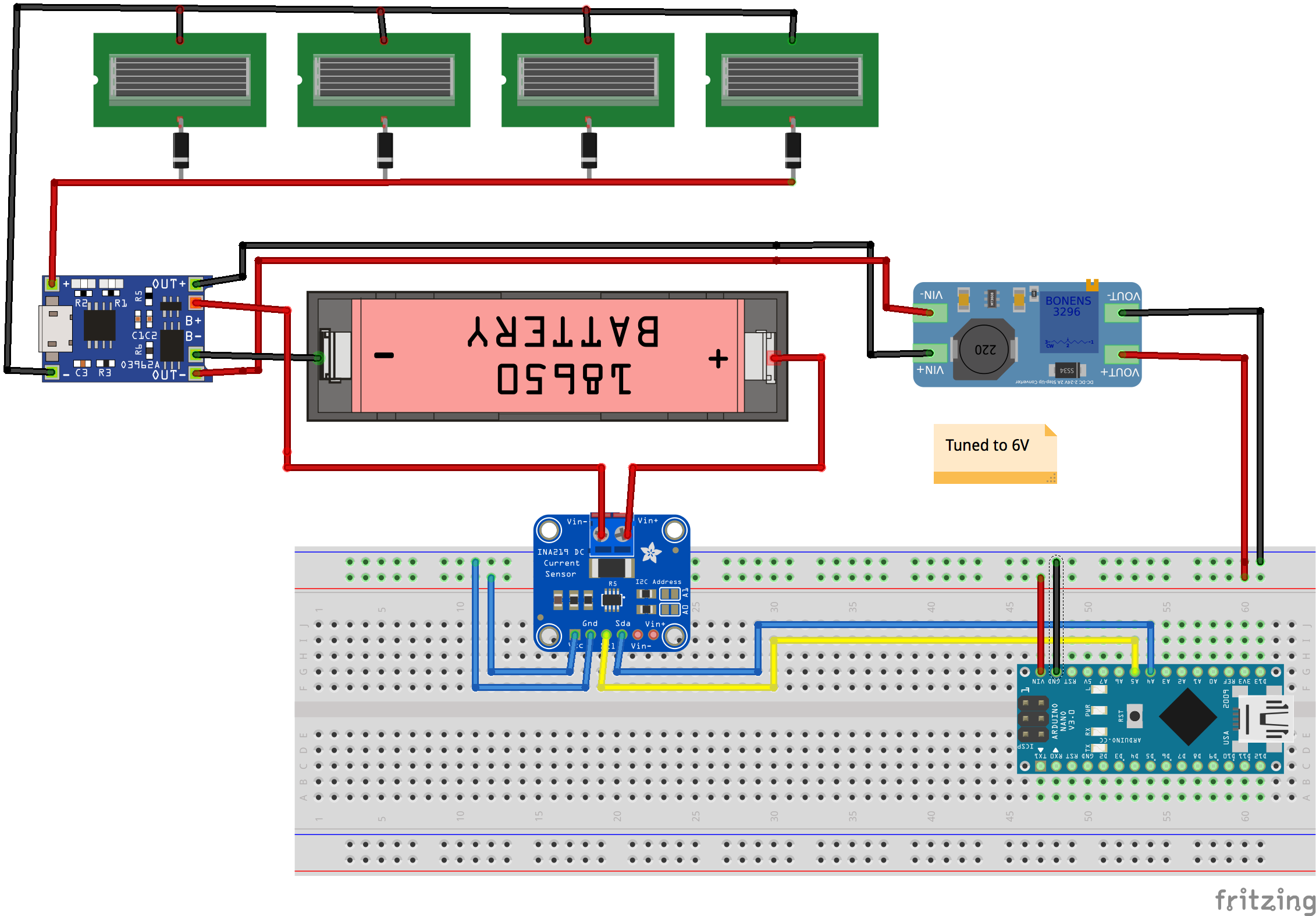
Monitoring Power
This is how we monitored battery voltage and current usage using the INA219 DC current monitor. This module communicates using I²C — refer to the schematic for the connections. A nice library for talking to the module already exists, which made this process really easy.
#include <Wire.h>
#include <Adafruit_INA219.h>

Adafruit_INA219 ina219;
float shuntvoltage = 0;
float busvoltage = 0;
float current_mA = 0;
float loadvoltage = 0;
float power_mW = 0;

void setup() {
  Serial.begin(115200);
  while (!Serial) {
      delay(1);
  }
  ina219.begin();
  ina219.setCalibration_32V_1A();
}

void loop() {
  shuntvoltage = ina219.getShuntVoltage_mV();
  busvoltage = ina219.getBusVoltage_V();
  current_mA = ina219.getCurrent_mA();
  power_mW = ina219.getPower_mW();
  loadvoltage = busvoltage + (shuntvoltage / 1000);
  Serial.print("Load Voltage:  "); Serial.print(loadvoltage); Serial.println(" V");
  Serial.print("Current:       "); Serial.print(current_mA);  Serial.println(" mA");
  Serial.print("Power:         "); Serial.print(power_mW);    Serial.println(" mW");
  Serial.println();
  delay(1000);
}
Using the Power Monitor to Set the Next RTC Alarm
Finally, this is how we used the voltage to predict the optimal duration between alarms. The method was a bit crude — if anyone has any better ideas, please get in touch!
#include <DS3232RTC.h>
#include <Adafruit_INA219.h>
#include <Wire.h>

int led = LED_BUILTIN;

// INA219 - Power Monitor
Adafruit_INA219 ina219;


void setup() {
  Wire.begin();
  pinMode(led, OUTPUT);

  // initialise INA219 - Power Monitor
  ina219.begin();
  ina219.setCalibration_32V_1A();
}

void loop() {
  digitalWrite(led, HIGH);
  delay(3000);
  reset_alarm();
}

void reset_alarm(){
  RTC.alarmInterrupt(ALARM_1, true);
  RTC.squareWave(SQWAVE_NONE);
  setTime(0, 0, 0, 0, 0, 1970);
  RTC.set(now());
  int wait_time = get_wait_time_from_voltage();
  // set new alarm
  RTC.setAlarm(ALM1_MATCH_MINUTES, 0, wait_time, 0, 0);
  // clear old alarm flag - turning off system
  RTC.alarm(ALARM_1);
}


int get_wait_time_from_voltage(){
  float shuntvoltage = ina219.getShuntVoltage_mV();
  float busvoltage = ina219.getBusVoltage_V();
  float loadvoltage = busvoltage + (shuntvoltage / 1000);

  // Samsung 18650 % capacity at a given voltage
  // batt_voltages            0.0, 3.4, 3.5, 3.6, 3.7, 3.8, 3.9, 4.0, 4.1, 4.2, 4.5
  // batt_percentages           0,   0,   9,  22,  52,  64,  75,  84,  93, 100, 100
  int wait_time;
  if (loadvoltage < 3.6) wait_time = 55;
  else if (loadvoltage < 3.8) wait_time = 25;
  else if (loadvoltage < 4.0) wait_time = 15;
  else if (loadvoltage < 4.1) wait_time = 10;
  else wait_time = 3;

  return wait_time;
}
🔗 Get The Smart Buoy Code On Github 📔
Thanks for reading

Thanks for reading this tutorial. This has been the third step in building our Smart Buoy, check out our next tutorial to see how we built the Buoy and base station, and deployed it to the (drumroll please) ocean…
Part 1: Making wave and temperature measurements
Part 2: GPS, Radio (NRF24) and SD Card Module
Part 3: Scheduling Power to the Buoy
Part 4: Waterproofing, Dashboards and Deploy!
We hope you enjoyed this article. If you like the style, check out T3chFlicks.org for more tech-focused educational content as well as all the fun stuff we do on YouTube (Instagram, Facebook, Twitter).


